-
On the Water Source dialog box, click on the Place New Water Source button. A water source symbol will appear on your mouse cursor. Do not worry if this is not the symbol you want to use to represent the water source. You will have the ability to change the symbol once it appears on the design.
-
Click one time to set the location of the water source symbol on the design screen.
-
Rotate the symbol to the desired angle and click a second time to complete the placement process and return to the Water Source dialog box.
-
Enter a description for the water source in the Description text box.
-
To change the symbol on the drawing that represents the water source, click on the drop down arrow to the right of the Symbol label to view the available symbol choices. Click one time on the symbol to assign to the selected water source.
-
To assign a to the symbol, click on the Color button. Click on the color of your choice or enter the Red, Green, and Blue values in the associated text boxes. Click on the OK button to accept the color assignment.
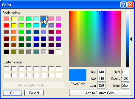
Select a color assignment and click on the OK button.
-
To insert a water meter into the design, select Meter from the Water Source Type drop down menu.
-
In the Water Meter Size location, click on the down arrow to view a list of the available meters. Select a water meter from the resulting menu by clicking on the selection with the left mouse button.
-
In the Elevation text box, enter the elevation at the water meter location. During the hydraulic calculations, the software will compare this elevation assignment to the elevation assignment of other system components and determine a gain or loss in design pressure.
-
Enter the available at the water meter in the Static Pressure text box. If Feet is selected as the Units of measurement, enter the pressure in PSI. If Meters is selected as the Units of measurement, enter the pressure in Bars.
-
Enter the maximum allowable velocity through the service line in the Maximum Service Line Velocity text box. If Feet is selected as the Units of measurement, enter the velocity in Feet per Second (ft/s). If Meters is selected as the Units of measurement, enter the velocity in Meters per Second (m/s).
-
In the Pipe Category drop down menu, select a pipe category for the service line from the listing by clicking on the selection with the left mouse button. The service line refers to the pipe connecting the city main to the water meter.
-
Once a category of pipe is chosen, select the pipe size from the Pipe Size drop down menu by clicking on the selection with the left mouse button.
-
Enter the length of the service line in the Length text box. If Feet is selected as the Units of measurement, enter the length in feet. If Meters is selected as the Units of measurement, enter the length in meters.
-
The maximum recommended flow of water through the water meter and the available at the water meter will be displayed in the dialog box. If necessary, you may change the maximum recommended flow of water through the water meter. To override the recommended flow, click on the Override Recommended Flow box with the left mouse button until a checkmark appears in the box. Enter a new flow in the maximum recommended flow text box.
-
Click on the Insert Water Source Data button to place the water meter information on the design screen. Adjust any of the font settings as necessary and click on the Place Text Table button. Set one point on the design screen for the top left corner of the table.
-
Click on the Close button exit the dialog box.