Lighting Calculations
Lighting Calculations
Lighting Calculations
Menu: |
Lighting
 Lighting Calculations Lighting Calculations |
Toolbar Icon: |

|
The Lighting Calculations command
will calculate the total wattage of all fixtures connected to each transformer
on the design. The calculations will also determine the highest voltage
drop, the lowest voltage drop and the voltage variance in each lighting
system. In addition, the command will size the wire or cable from each
transformer to the lighting fixtures based on the Maximum
Allowable Voltage Drop.
To automatically size the lighting wire or
cable:
Click on the Size
Wire to Recommended Gauge checkbox until a checkmark appears
in the box. If the box is not checked, the software will not size
the wire or cable.
Enable the Color
Code Wire by Zone check box by clicking on the selection with
the left mouse button until a checkmark appears in the box to color
code each zone of wire based on the settings in the Options
dialog box on the Lighting tab. If this feature is disabled,
the wire will be colored based on the settings for each wire size
in the Lighting Wire/Cable
Placement command.
When automatically sizing
accent lighting wire or cable, it is necessary to know the maximum
acceptable voltage drop within a circuit. In the Maximum
Allowable Voltage Drop text box, type in the acceptable value.
When sizing wire automatically,
a label is placed on the
design screen to indicate the size of the wire. To label every
piece of wire on the design, set the Wire
Label Locations to All
Wire. To label only the transitions from size of wire
to another, select Size Transitions
from the drop down menu.
Select
each wire size to use during the sizing process in the Wire Selection
box. Click on each wire size selection with the left mouse button
until a checkmark appears in the box. A wire size that has not been
selected will not be used during the wire sizing process.
Click on the Calculate
button to automatically size the wire or cable and open the Voltage Drop Calculations dialog
box.
Click on the Close
button to exit the command without sizing the wire or cable.
Viewing and inserting voltage information:
Once calculated, the voltage information will appear
in the Lighting Calculations dialog
box.
Click on the Select
button to the right of a Transformer description or Zone Number to
select the equipment on the design screen.
Click on any lighting component associated with the
system to view specific information on the equipment.
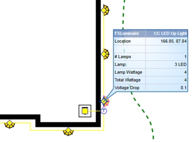
Voltage data on a selected lighting
fixture
| Symbol Legend
for Voltage Drop Calculations |

|
Fixture disconnected from lighting
circuit |

|
Wiring disconnected
from the lighting circuit |
Click on the Insert
Calculation Data button to place the voltage information on
the design screen. Adjust any of the font settings as necessary
and click on the Place Text Table
button. Set one point on the design screen for the top left
corner of the table.
Click on the X
in the top right corner of the dialog box to close the box.
Note:
Back to All Topics