Valve Notations
Valve Notations
Valve Notations
|
Menu:
|
Irrigation  Zoning Zoning
|
|
Toolbar Icon:
|

|
The Zoning command will allow you to place Valve Notation symbols on the design or assign a zone number to the selected sprinkler symbols or control valves. There are multiple valve notation symbols from which to choose. Each notation includes the zone assignment number, the size of the control valve, and the flow of water through the valve.
To place valve notation symbols on the design screen:
-
Select the zone number from the Zone area by clicking on the selection one time with the left mouse button. use the scroll bar on the right side of the dialog box to view all of the zone numbers.
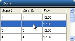
Select a Zone # for Valve Notation Placement
-
Click two times into a zone number box in the Cont. ID column and enter a controller identifier if necessary and station number.
If nothing is entered in the Cont. ID column, the associated Zone # will automatically be assigned as the Controller ID in the valve notation symbol.
If there is more than one controller on the design, it may be necessary to assign an identifier to each zone to help determine which control valves are associated to which controllers. For example, assume there are 16 zones on the design to assign to two 8 station controllers. The first controller might be assigned an identifier such as A. Zones 1 through 8 will have Controller ID's of A1 through A8. Controller number two will be assigned an identifier of B. Zones 9 through 16 will be assigned Controller ID's of B1 through B8.
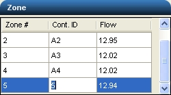
Entering a Controller ID and Station Number
-
Click on the drop down arrow to the right of the Notation Symbol label to view the available symbol choices. Click one time on the desired valve notation symbol.
-
Enter a value for the size of the notation symbol on the design screen in the Symbol Size box. The size is related to the units of measurement setting. For example, a setting of 10 will equate to 10 feet or 10 meters depending on the units of measurement setting.
-
Click on the Apply button to place the symbol on the design screen. If a symbol already exists on the drawing, the Apply button will update the information in the notation symbol such as the controller/station identifier, the zone flow and control valve size.
-
The valve notation symbol will appear on the mouse cursor. Drag the symbol to the desired location and set a point on the design for the center of the valve notation symbol by clicking one time with the left mouse button.
-
Click on the Close button to exit the dialog box.
Note:
Back to All Topics