Piping Sprinklers or Valves
Piping Sprinklers or Valves
Piping Sprinklers or Valves
When drawing pipe manually on the design screen, it is not necessary to end the pipe at each sprinkler or valve symbol. You may draw one continuous piece of pipe, however, the pipe must pass within six inches of any sprinkler, control valve, backflow device or water source location for the program to consider the pipe connected to the device. Pro Contractor Studio� will automatically break the pipe at each symbol location during the Automatic Pipe Sizing process.
To be more specific, when you select a symbol on the drawing screen the selection handle  appears indicating the base point or insertion point of the symbol. The pipe must start or stop within 0.50 feet of this location. If you are not sure of the insertion point, try to set points within .5 feet of the center of a sprinkler, control valve, or backflow device symbol.
Refer to illustration one below. Notice that we began drawing the pipe on the left side of the sprinkler layout. You can set a point at each sprinkler location per the illustration, or you can set a point at the first sprinkler symbol on the left and a second point at the last sprinkler on the right. As long as the pipe passes within six inches of the insertion points of the sprinklers in between, the pipe will be broken at each sprinkler location during the Automatic Pipe Sizing command.
You can drag the mouse cursor close to an irrigation symbol and press the right mouse button to "snap" onto the symbol. This is the best method to insure the pipe is connected to the irrigation symbol.
Once you reach the final sprinkler on the row, press the Enter key on the keyboard to end the pipe.
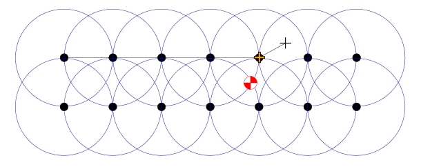
Illustration 1
Now click on the Draw Pipe button in the Pipe Placement command and begin drawing more pipe between the sprinklers on the second row. Once you have drawn the pipe through the sprinkler symbols, press the Enter key to end the pipe. The pipe size labels will appear above or below the pipe depending on the direction in which you draw the pipe.
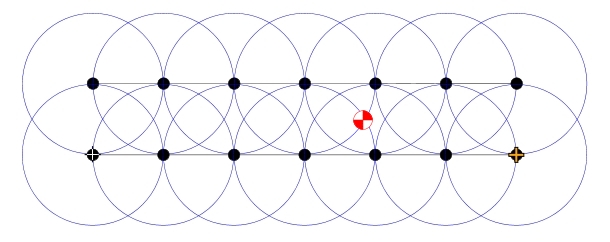
Illustration 2
Now that you have drawn pipe between the sprinklers on each row, you can draw pipe connecting the two rows. Click on the Draw Pipe button in the Pipe Placement command and draw a piece of pipe connecting the two rows. Set a point with the left mouse button close to a piece of pipe on each of the sprinkler rows. Press the Enter key and the pipe will be drawn between the rows. Refer to illustration three below.
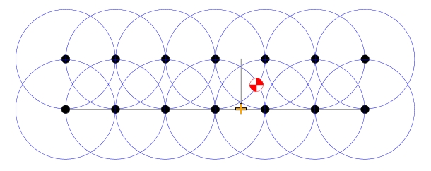
Illustration 3
Click on the Draw Pipe button in the Pipe Placement command and draw a single piece of pipe by first clicking on the vertical piece running between the top and bottom rows. Drag the mouse to the control valve symbol and press the right mouse button to "snap" onto the control valve symbol. Press the Enter key to end the piece of pipe and the Esc key to return to the Pipe Placement dialog box.
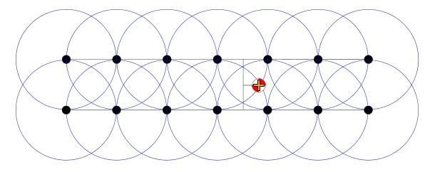
Illustration 4
Pipe each of the irrigation control valves together in this same manner all the way back to the water source. Be sure to connect the backflow prevention device as well.
The software will break pipe at each intersection formed by a tee or cross fitting during the Automatic Pipe Sizing command. In illustration five below, we have circled the intersections where the pipe will be broken. This will ensure that the pipe is sized correctly and that the system hydraulics can be calculated correctly.
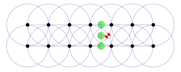
Illustration 5
Back to All Topics