Pipe Sizing Options
Pipe Sizing Options
Pipe Sizing Options
|
Menu:
|
Irrigation  Pipe Sizing Pipe Sizing
|
|
Toolbar Icon:
|

|
The Pipe Sizing Options command will allow you to adjust settings to control the type and size of pipe used in the design as well as the velocity of the water traveling through the system and the allowed pressure variance. In addition, you can choose to color code pipe for each zone based on the settings in the Options dialog box on the Irrigation tab, or allow the program to color the pipe based on the settings for each pipe size in the Pipe Placement command.
To adjust the option setting before automatically sizing lateral line or mainline pipe:
-
On the Automatic Pipe Sizing dialog box, click on the Sizing Options tab.
-
Select the category of pipe to use when sizing from the Pipe Category drop down menu by clicking on the selection one time with the left mouse button.
-
Select each pipe size to use during the sizing process in the Check Pipe Sizes Used for Sizing box. Click on each pipe size selection with the left mouse button until a checkmark appears in the box. A pipe size that has not been selected will not be used during the pipe sizing process. For example, in the illustration below, we selected Class 200 PVC and disabled 1/2" and 1 1/4" pipe. When sizing the mainline or lateral line pipe, these two sizes will not be used during the process.
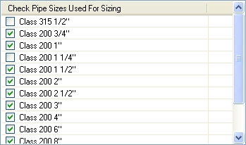
1/2" and 1 1/4" Pipe Disabled for Pipe Sizing
-
Type in the maximum allowed velocity for the mainline and lateral line pipe in the associated text boxes. It is recommended that you not exceed a velocity of seven feet per second. The velocity should be entered as either feet per second (ft/s) or meters per second (m/s) depending on the Units of measurement selected for the design.
-
Type in the percent allowable pressure variance in the Percent Allowable Pressure Variance text box. In all piping situations, there will be a pressure difference between the first and last sprinkler in the zone. The difference in pressure should be controlled to maintain system performance at the nozzle. Increased pressure may also increase the precipitation rate causing one portion of the zone to receive more water than another. The default setting is 10%. It is not recommended that the number be set greater than 32%. For example, a value of 10% should be entered as 10 and not 0.10.
-
When sizing pipe with the automatic pipe sizing function, a label is placed on the design screen to indicate the size of the pipe. To label every piece of pipe on the design, set the Label Locations to All Pipe. To label only the transitions from size of pipe to another, select Size Transitions from the drop down menu.
-
Enable the Color Lateral Line Pipe per Zone check box by clicking on the selection with the left mouse button until a checkmark appears in the box to color the mainline pipe and color code each zone of lateral line pipe based on the settings in the Options dialog box on the Irrigation tab. If this feature is disabled, the pipe will be colored based on the settings for each pipe size in the Pipe Placement command.
-
Click on the Lateral Line Pipe or Mainline Pipe tab to continue the pipe sizing process.
-
Click on the Close button to exit the dialog box.
Note:
-
Adjusting the velocity and pressure variance settings can greatly affect the sizing of pipe within the system. If the sizes are not satisfactory, you may adjust the settings and resize the system until you are pleased with the results. If you are satisfied with part of the system but unsatisfied with other parts, you may resize smaller segments of the system. Simply select zones to resize prior to enacting the Automatic Lateral Line Pipe Sizing command.
-
You can adjust the Pipe Connection Distance and the size and color of the pipe size labels on the design screen in the Options command on the Irrigation tab.
-
You can move or reposition the pipe size labels using the Properties command or the Move Pipe Labels command.
Back to All Topics