Mainline Pipe Sizing
Mainline Pipe Sizing
Mainline Pipe Sizing
|
Menu:
|
Irrigation  Pipe Sizing Pipe Sizing
|
|
Toolbar Icon:
|

|
The Mainline Pipe Sizing command will size all mainline pipe from the furthest control valve back to the water source location. The command will automatically detect any mainline loop piping network and size the pipe based on the Hardy Cross method of balancing flows and pressure loss. In addition, the command will allow for single valve operation or multiple control valves operating at one time. The command will label all mainline pipe or transitions from one size of pipe to another based on the Label Locations setting on the Sizing Options tab.
Before you may size mainline pipe, it must meet the following criteria:
Mainline
-
One or more control valves must exist on the drawing screen.
-
Each control valve must be assigned to a zone number using the Zoning command.
-
A water source symbol must be placed on the design screen using the Water Source command.
-
The mainline pipe must be connected from each control valve all the way back to a water source location.
-
If a backflow device or master valve is on the design screen, it must be connected to the mainline pipe.
To automatically size mainline pipe on the design screen:
-
On the Automatic Pipe Sizing dialog box, click on the Sizing Options tab and adjust the settings as necessary.
-
On the Automatic Pipe Sizing dialog box, click on the Mainline Pipe tab.
-
If each control valve in the system will operate individually, select Independent valve operation from the drop down menu and click on the OK button to begin the pipe sizing process. If more than one control valve will operate at a time, proceed to step 4 below.
-
If more than one control valve will operate at a time, select the Simultaneous valve operation from the drop down menu.
-
To run control valves at the same time, it is necessary for you to group the valves into individual Run Sets. Each Run Set is a group of control valves that will operate simultaneously. You may create as many different Run Sets as required. To create a new Run Set, click on the Add Run Set button.
-
To place control valves into the Run Set, click on the desired Zone number in the list on the left side of the dialog box until a checkmark appears in the box. The flow of the selected control valves will be displayed in the Total Run Set Flow text box.
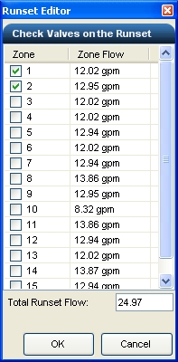
Zones 1 and 2 combined to create a run set with a total flow of 24.97 GPM.
-
To delete a Run Set from the list, select the desired Run Set in the list and click on the Delete Run Set button. Answer Yes in the resulting box to complete the process. You cannot undo this action.
-
To edit the list of control valves assigned to a Run Set, click on the Edit Run Set button.
-
Once all possible Run Sets have been created, click on the OK button to begin the pipe sizing process.
-
Click on the Close button to exit the dialog box.
Note:
-
A Run Set is a list of control valves that will operate simultaneously when the Simultaneous valve operation feature is selected.
-
The Run Set configuration along with the adjustment of the velocity and pressure variance settings can greatly affect the sizing of pipe within the system. If the sizes are not satisfactory, you may adjust the settings and resize the system until you are satisfied with the results.
-
The mainline pipe will be broken into individual pieces of pipe between each control valve symbol and the water source. In addition, the pipe will be broken at intersections usually formed by tee or cross fittings.
-
You can adjust the Pipe Connection Distance and the size and color of the pipe size labels on the design screen in the Options command on the Irrigation tab.
-
You can override the pipe size label location on the design screen using the Properties command. Select a piece of pipe and click on the Override Label Point checkbox. The pipe size label will attach to the mouse cursor. You can then place the label in a new location by clicking on the design screen with the left mouse button. To return the label to its original position, un-check the Override Label Point checkbox.
-
To remove a label from the design screen, erase the text to the right of the Label location in the Properties command.
-
You can manually adjust the line type or width of the mainline pipe in the Layer Manager.
Back to All Topics