Layer Manager
Layer Manager
Layer Manager
The Layer Manager appears at the top of the application just below the menu system and main toolbar icons.

Layer Manager drop down menu
You can associate similar types of objects by creating layers and assigning them to the same layer. For example, you can put all lines for houses, garages and sheds on a Buildings layer. Lines for curbs, driveways, sidewalks and patios might go on a Hardscape layer. Additional lines for fencing or property lines might be drawn on a Property layer.
You can then control the following:
-
Whether objects on a layer are visible or invisible on the design screen
-
What color is assigned to all objects on a layer
-
What default line style, width and scale are assigned to all objects on a layer
You can create new layers for drafting entities to include the linear length in the material list or estimate. For example, you may need to create layers for drafting metal edging or concrete mow curbs. A layer may need to be created to count the linear length of three rail fencing. You can assign layers to be included in the material list or estimate in the Layer Linear Lengths command.
To ensure that all drawings have at least one layer, every drawing includes a layer named 0. You cannot delete or rename Layer 0.
When closed, the Layer Manager displays the current drawing layer and its characteristics. The current drawing layer is indicated by the  symbol to the left of the layer name in the drop down menu or Layer Manager window.
To add a layer to the list:
-
Click on the drop down arrow  to the right of the Layer Manager.
-
Click on the Add Layer button at the bottom of the Layer Manager.
-
A New Layer X will be added to the list.
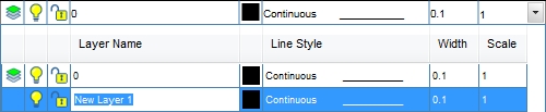
New Layer 1 added to the list of layers
-
Type the desired layer name in the Description area replacing the current layer name of New Layer X. The layer name can be up to 255 characters in length including letters, numbers and spaces. Layer names cannot include the following characters: < > / \ � : ; ? * | = �
-
To assign a to all entities drawn on the layer, click on the Color button. Click on the color of your choice or enter the Red, Green, and Blue values in the associated text boxes. Click on the OK button to accept the color assignment.
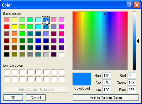
Select a color assignment and click on the OK button.
-
Each new layer is automatically assigned to the Continuous line style. You can use line styles to distinguish entities from one another visually and make your drawing easier to read. Click on the line style name and select the desired line style from the drop down list to assign to each new entity drawn on this layer.
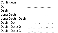
Layer Manager line styles
-
Enter a value for the width of the line style in the Width text box. Enter the values per linear unit. The width will be applied to all entities drawn on the layer. The width of the line styles drawn on the layer will help differentiate entities on the design screen. For example, by assigning various widths to different layers, you can easily differentiate between new and existing construction. All new layers are set to the width as indicated in the Tools > Options > General command in the Line Thickness text box.
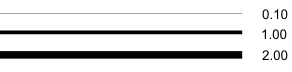
Continuous line style at varying widths
-
Enter a value for the scale of the line style in the Scale text box. The scale represents a factor indicating the number of times the pattern in the line style will repeat itself. By default, all new line styles are set to a scale of 1.00 unit. The smaller the scale, the more repetitions of the pattern are generated. If the scale setting becomes too small or the line is too short, the line may not display one full pattern and the line will be displayed as a continuous or solid line.
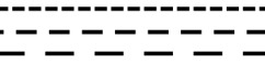
Dash line style at varying scales
- To close the Layer Manager, click anywhere on the screen outside of the Layer Manager box.
In the Layer Manager you can turn the visibility of a layer on or off. You cannot turn off the current drawing layer. If a layer is invisible, it will not print.
To turn a layer on or off on the design screen:
-
Click on the light bulb icon to the left of the layer name. If the bulb is illuminated  , the layer will be visible. If the bulb is darkened
  , the layer will be invisible.
In the Layer Manager you can lock a layer to prevent the manipulation of the entities on the layer or unlock the layer to allow entities to be manipulated. You cannot lock the current drawing layer.
To lock or unlock a layer:
-
Click on the padlock icon to the left of the layer name. If the padlock is in the unlocked position  , the layer is unlocked. If the padlock is in the locked position
  , the layer is locked.
You can select an entity on the design screen and the entities layer assignment will display in the closed Layer Manager. You can quickly turn off or lock the layer by clicking on the light bulb or padlock icons to the left of the layer name. You cannot turn off or lock the current drawing layer.
There may be times when you need to increase or decrease the width of all layers simultaneously. This is especially true if you have imported an AutoCAD� DWG drawing file.
To change the width of all layers at one time:
-
Click on the Line Thickness Scale Percentage drop down menu and select a percentage increase or decrease from the listing.
-
Click on the Apply button to increase or decrease the width settings for all layers.
To speed up the program during the design process, it may be necessary to temporarily turn off the fill patterns on plant symbols and other entities.
To turn on or off the fill patterns:
-
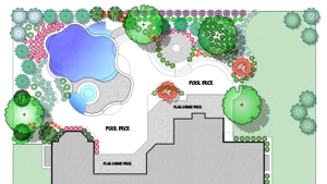
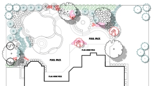
Click on the Show Fills box with the left mouse button until a checkmark appears in the box to make the fill patterns visible on the design screen. Click on the box until a checkmark disappears to make the fill patterns invisible on the screen.
|
|
|
|
Show Fills Checkmark On
|
Show Fills Checkmark Off
|
To quickly turn on or off sprinkler arc patterns, pipe size labels and more:
-
Click on each selection with the left mouse button until a checkmark appears in the box to make the entities visible on the design screen.
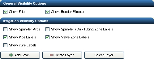
Check boxes with sprinkler arcs, zone labels and wire labels turned off on the design screen
-
To close the Layer Manager, click anywhere on the screen outside of the Layer Manager box.
To select all entities on the current drawing layer:
-
Click on the layer name to make it the current drawing layer. The current drawing layer is identified by the  symbol to the left of the layer name.
-
Click on the Select Layer button at the bottom of the Layer Manager. All entities on the current layer will be selected on the design screen. You can then use other commands to manipulate the selected entities such as the Move or Rotate commands. The Move to Front or Move to Back commands used in conjunction with the Select Layer command is an easy way to move sprinkler symbols on top of pipe or move pipe underneath all irrigation symbols.
To delete a layer and its entities from the design screen:
-
Click on the space to the left of the layer name to make the layer the current layer. The current drawing layer is indicated by the symbol to the left of the layer name in the drop down menu or Layer Manager window.
-
Click on the Delete Layer button at the bottom of the Layer Manager.
-
Click on Yes in the resulting box to delete the layer and all of its entities from the drawing. You cannot undo this action.
-
To close the Layer Manager, click anywhere on the screen outside of the Layer Manager box.
Note:
-
You cannot change all of the characteristics of layers created by the software such as the sprinkler layers, pipe layers, etcetera.
-
We recommend that you create multiple new layers to organize your design rather than drawing all entities on layer 0.
-
Layer names can be up to 255 characters in length including letters, numbers and spaces. Layer names cannot include the following characters: < > / \ � : ; ? * | = �
-
Colors and settings for certain items such as zone assignment numbers, pipe size labels and pipe colors are set in the Irrigation Options command or the Pipe Placement dialog box.
-
The color assignment for an irrigation symbol is set in the placement command for the equipment.
-
If a layer is set to invisible, it will not print during the printing process.
-
If you consistently use a specific layering scheme, you can create a drawing template with preset layers, line styles, and colors already assigned.
Back to All Topics