-
Click on the Irrigation tab.
-
When automatically sizing lateral line or mainline pipe, or calculating system hydraulics, pipe must be connected within a set distance of the insertion point of an irrigation symbol, or the end point of another piece of pipe. The default setting is 6 inches. If the pipe is not connected properly, the software will not consider it connected to the symbol or another piece of pipe. If pipe from two different zones end within the connection distance, the software will consider the two zones to be connected. To change the default distance setting, click on the Pipe Connection Distance drop down menu and click on the distance of your choice.
-
When calculating the system hydraulics, you can include a pressure loss through fittings based on the percent of loss in the mainline and lateral line pipe. For example, if there is a 7.5 PSI loss in the mainline and lateral line pipe and you have a fittings loss entered as 10%, the pressure loss for the fittings would be equal to 0.75 PSI. Enter the pressure loss as a percent of the pipe loss in the Fittings Loss % text box. Enter a percent of loss of 10 percent as 10.00 and not 0.10.
-
When designing in Metric units of measurement, click on the Metric Flow Units drop down menu and click on the desired units of measurement for spray and rotary nozzles.
-
In the Symbol Scale Factors area, type in the desired factor in the text box associated with each different type of symbol. This scale factor setting will increase or decrease the size of the symbols when they are placed on the design screen. To increase or decrease the size of existing symbols on the design, enter the Symbol Scale Factors and click on the Apply button.
The irrigation option settings for Symbol Scale Factors are saved with a drawing. In addition, the settings are saved for each output scale. For example, the settings for an output Scale in the Drawing Page Setup command of 1" = 20' may be different from the settings for an output Scale of 1" = 10'. When you change the output Scale setting for the drawing in the Drawing Page Setup command, the Symbol Scale Factors will change accordingly.
-
In the Sprinkler Arc Patterns area, enter a default thickness or width for the arcs representing the sprinkler wetting pattern in the Arc Thickness text box.
Select an Arc Color by clicking on the colored rectangle one time with the left mouse button to open the Color dialog box. Select a color and click on the OK button. For more information within the Color dialog box, press the right mouse button for What's This help or click on the Question Mark near the top right corner of the dialog box and then click on an item.
Click on the Line Style drop down menu and click on a line style name. Select the desired line style from the drop down list to assign to all sprinkler arc patterns on the design.
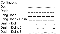
Available sprinkler arc line styles
To adjust the thickness, color, or line style of the existing arc patterns on the design, enter or select the values and click on the Apply button.
-
A number will be assigned to each sprinkler or control valve symbol designating the zone assignment. Enter the height of the font in the Sprinkler Label Text Size or Valve Label Text Size text box. The height is related to the units of measurement setting. For example, a setting of 10 will equate to 10 feet or 10 meters depending on the units of measurement setting.
Select a Sprinkler Label Color or Valve Label Color by clicking on the colored rectangle one time with the left mouse button to open the Color dialog box. Select a color and click on the OK button. For more information within the Color dialog box, press the right mouse button for What's This help or click on the Question Mark near the top right corner of the dialog box and then click on an item.
To adjust the size or color of the existing zone assignment numbers on the design, enter or select the values and click on the Apply button.
-
Under the Pipe Size Label Settings header, adjust the characteristics for the pipe size labels as necessary.
-
Mainline pipe is usually drawn in a different line style than lateral line to help distinguish between the two on the design screen. The default line style for mainline pipe is a Dash line style. To change the default linestyle setting for the mainline pipe, click on the Line Style drop down menu and click on the style of your choice.
Mainline is usually drawn with a thickness greater than lateral line pipe. Enter a default thickness or width for the mainline pipe in the Mainline Line Thickness text box.
In the Line Scale text box, type in the desired scale setting for the mainline pipe. Depending on the output scale of the design or the size of the design screen, it may be necessary to adjust the line type scale or distance between the dashes forming the mainline. For example, if you print or plot a design at a 1" = 30' scale, the dashes forming the mainline may be so close together that the line appears to be a solid line rather than a dashed line. It is recommended that you draw a piece of mainline on the screen and print the drawing at the desired scale to determine what setting is best for your project.
Lateral line pipe is usually drawn with a line that is slightly smaller in width than the mainline. Enter a default value for the thickness of the lateral line pipe in the Lateral Line Thickness text box.
To adjust the line style and scale setting of the existing mainline pipe on the design, enter or select the values and click on the Apply button.
-
If the Color Lateral Line Pipe per Zone check box is enabled when sizing pipe using the Automatic Pipe Sizing command, the color of the mainline pipe and the color of the lateral line zones will be based on the settings under the Auto Pipe Colors area. If the Color Lateral Line Pipe per Zone check box is disabled, the pipe will be colored based on the settings in the Pipe Placement command. To select the color for the mainline pipe, click on the color button to the right of the Mainline label one time with the left mouse button to open the Color dialog box. Select a color and click on the OK button. To set the alternating colors for the lateral line zones, click on each color button one time with the left mouse button to open the Color dialog box. Select a color and click on the OK button. There are nine alternating colors used in color coding each lateral line zone.
-
Click on the Close button to exit the dialog box.