Hydraulics
Hydraulics
Hydraulics
|
Menu:
|
Irrigation  Hydraulics Hydraulics
|
|
Toolbar Icon:
|

|
The Hydraulics command will allow you to perform pressure loss calculations on any of the completed sprinkler zones within the irrigation design. The calculations include pressure loss through each component of the system, as well as the gain or loss in elevation, and the pressure loss through the service line. Typically, it is only necessary to calculate total pressure loss data on the largest zone and for the zone furthest from the point of connection or water source; however, you may perform hydraulic calculations on each zone on the design screen.
Before you begin calculations, you must size all lateral line pipe within the zone. You must size the mainline pipe from the control valve back to the point of connection. A water source and a control valve must exist for the zone and if applicable, you must place a backflow device and master valve.
To perform hydraulic calculations on a single sprinkler zone:
-
If each control valve in the system will operate individually, select Independent valve operation from the drop down menu.
-
Click on the Zone drop down menu and choose a zone number in the list by clicking on the selection one time with the left mouse button.
-
Once calculated, the Hydraulics command will allow you to select an object on the screen and view more detailed information on the equipment such as the size, length, flow, velocity, and pressure loss in an individual piece of pipe. To more easily see the components of the system that make up the selected zone, you can set a transparency level for the remainder of the drawing. This setting does not permanently affect the drawing in any way. It is strictly available to make the current zones components more visible.
Click on the Object Transparency drop down menu and choose the desired transparency level for all entities excluding those that make up the current selected zone. The default setting is High. A selection of None will not add transparency to any of the drawings entities. A selection of Full will completely hide all remaining entities on the design screen.
-
Arrows will appear on each piece of pipe associated with the current zone selection to indicate the direction of flow. In the Flow Arrow Size text box, enter a value for the arrow size.
-
Click on the Calculate Selected Zone button to calculate the system hydraulics.
-
Click on the X in the top right corner of the dialog box to close the box.
To perform hydraulic calculations on multiple zones running simultaneously:
-
If multiple control valves will operate at the same time, select the Simultaneous valve operation from the drop down menu.
-
To run control valves at the same time, it is necessary for you to group the valves into individual Run Sets. Each Run Set is a group of control valves that will operate simultaneously. You may create as many different Run Sets as required. To create a new Run Set, click on the Add Run Set button.
-
To place control valves into the Run Set, click on the desired Zone number in the list on the left side of the dialog box until a checkmark appears in the box. The flow of the selected control valves will be displayed in the Total Run Set Flow text box.
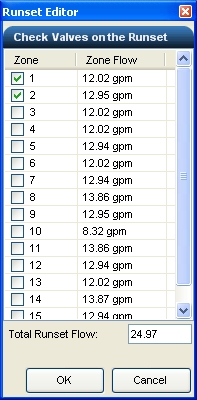
Zones 1 and 2 combined to create a run set with a total flow of 24.97 GPM.
-
To delete a Run Set from the list, select the desired Run Set in the list and click on the Delete Run Set button. Answer Yes in the resulting box to complete the process. You cannot undo this action.
-
To edit the list of control valves assigned to a Run Set, click on the Edit Run Set button.
-
Once calculated, the Hydraulics command will allow you to select an object on the screen and view more detailed information on the equipment such as the size, length, flow, velocity, and pressure loss in an individual piece of pipe. To more easily see the components of the system that make up the selected run set, you can set a transparency level for the remainder of the drawing. This setting does not permanently affect the drawing in any way. It is strictly available to make the current run set components more visible.
Click on the Object Transparency drop down menu and choose the desired transparency level for all entities excluding those that make up the current selected run set. The default setting is High. A selection of None will not add transparency to any of the drawings entities. A selection of Full will completely hide all remaining entities on the design screen.
-
Arrows will appear on each piece of pipe associated with the current run set selection to indicate the direction of flow. In the Flow Arrow Size text box, enter a value for the arrow size.
-
Once all possible Run Sets have been created, click on the Calculate Selected Run Set button to begin the hydraulic calculation process.
-
Click on the X in the top right corner of the dialog box to close the box.
Viewing and inserting hydraulic information:
-
Once calculated, the hydraulic information will appear in the Hydraulics Summary dialog box.
-
Click on any irrigation component associated with the selected zone or run set to view specific information on the equipment.
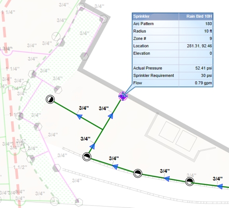
Hydraulic data on a selected sprinkler with the Object Transparency set to High
-
Click on the Insert Hydraulics Data button to place the hydraulic information on the design screen. Adjust any of the font settings as necessary and click on the Place Text Table button. Set one point on the design screen for the top left corner of the table.
-
Click on the X in the top right corner of the dialog box to close the box.
Note:
-
The change in pressure due to elevation is calculated by determining the difference in elevation from the water source to each component within the design. Each irrigation component may be assigned to an elevation using the Properties command.
-
On drip tubing zones, the hydraulic calculations include the loss through the control valve, the mainline, backflow, and water source. The hydraulic calculations on drip tubing zones does not include the loss in the tubing itself or the lateral line connecting the control valve to the tubing.
-
A Run Set is a list of control valves that will operate simultaneously when the Simultaneous valve operation feature is selected.
-
Select a single piece of equipment on the design to view information.
-
You can adjust the Pipe Connection Distance in the Options command on the Irrigation tab.
Back to All Topics