Drip Tubing
Drip Tubing
Drip Tubing
|
Menu:
|
Irrigation  Drip Tubing Drip Tubing
|
|
Toolbar Icon:
|

|
The Drip Tubing command will allow you to draw inline emitter tubing on the drawing screen. You may draw tubing as a shaded area or as individual line segments. You can also outline individual drip tubing line segments with a Drip Boundary.
|

|
|

|
|
Drip tubing drawn as a shaded area
|
|
Drip tubing drawn as line segments
|
The program will calculate how much tubing is located within a Drip Area and determine the flow for mainline pipe sizing or hydraulic calculations. When outlining individual drip tubing line segments with a Drip Boundary, the flow for any tubing that falls 100% inside of the boundary area will be totaled and used to size mainline pipe or to perform hydraulic calculations. To total the flow of a drip zone for mainline pipe sizing or hydraulic calculations, you must assign a Drip Area or Drip Boundary to a zone number using the Zoning command.
To place drip tubing on the drawing screen:
-
Click on the Manufacturer drop down menu and select the manufacturer of your choice.
-
The drip tubing selections associated with the chosen manufacturer will be displayed under the Drip Tubing Selection header. Click on the desired tubing selection one time with the left mouse button.
-
To assign a to the tubing, click on the Color button. Click on the color of your choice or enter the Red, Green, and Blue values in the associated text boxes. Click on the OK button to accept the color assignment.
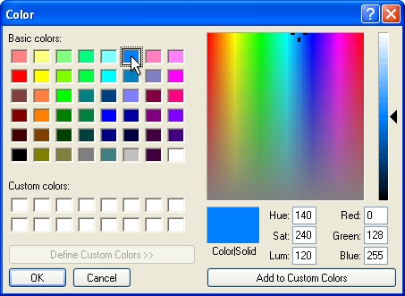
Select a color assignment and click on the OK button.
-
Select the default pressure setting for the tubing by clicking on the Pressure/Flow drop down menu and clicking on the selection of your choice.
-
Under the Draw Options header, click on the Draw As drop down menu. Select Single Drip Line to draw the tubing as individual line segments on the design screen. Select Drip Area to draw the tubing as a shaded area. Select Drip Boundary to outline individual drip tubing line segments on the design screen to calculate the flow for mainline pipe sizing and hydraulic calculations.
-
If Single Drip Line is selected as the draw option, the draw method will be set to Draw Manual.
Click on the Add  button and follow the prompts in the Status Bar.
Set two or more points on the design screen by clicking with the left mouse button and press the Enter key to end the line. Continue placing tubing as necessary.
Press the Esc key to end the command and return to the Drip Tubing dialog box.
-
If Drip Area is selected as the draw option, enter the distance between the rows of tubing in the Row Spacing text box. This will allow the program to calculate how much tubing is located within the area. If Feet is selected as the Units of measurement, enter the distance in inches. If Meters is selected as the Units of measurement, enter the distance in millimeters.
-
If Drip Boundary is selected as the draw option, outline an area of individual drip tubing line segments.
-
If either Drip Area or Drip Boundary is selected as the draw option, chose the area selection method from the drop down menu. Draw Manual will allow you to set points to outline the area. From Selection will allow you to select the entities that enclose the area. From Point will allow you to set a point inside of a closed area.
-
Click on the Add button and follow the prompts in the Status Bar.
-
Click on the Close button to exit the dialog box.
Note:
-
When drawing drip tubing as single lines or by manually outlining an area, you can press the Esc key to back up and remove points set for the line or area.
-
To total the flow of a drip zone for mainline pipe sizing or hydraulic calculations, you must assign a Drip Area or Drip Boundary to a zone number using the Zoning command.
-
If the Polar Angle is turned on, the line will "snap" to preset angles based on the Polar Angle setting.
-
The Anchor Point  will move to the location of the last point set on the screen. The distance and angle from the Anchor Point location is shown in the Status Bar at the bottom of the screen.
-
You can select drip tubing and click on the Properties command to see the flow of the selection.
-
Set the cost associated with each piece of equipment, the part number and the tied assembly assignment in the Equipment Costs command.
-
Expand or contract sections as required.
Back to All Topics