Drainage Pipe
Drainage Pipe
Drainage Pipe
Menu: |
Drainage
 Drainage Pipe Drainage Pipe |
Toolbar Icon: |

|
The Drainage Pipe command allows
you to draw drainage pipe on the drawing screen.
To draw pipe on the design screen:
Click on the Manufacturer
drop down menu and select the manufacturer of your choice. You
can add, delete or rename the
manufacturers.
The pipe selections associated with the chosen manufacturer
will be displayed under the Pipe
Selection header. Click on the desired pipe selection
one time with the left mouse button. You can add,
delete or rename the pipe selections.
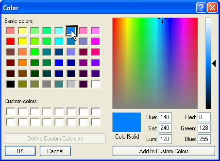
To assign a to the pipe, click
on the Color button. Click
on the color of your choice or enter the Red, Green, and Blue values
in the associated text boxes. Click on the OK
button to accept the color assignment.
Select a color assignment and click on the OK button.
To begin drawing pipe on the design, click on the
Draw Pipe button.
Set two or more points to draw a piece of pipe. You
may press the Esc key to "backup"
and remove points set while drawing pipe. Press the Enter
key to end a piece of pipe. Continue placing additional pipe
as necessary.
Press the Esc
key to end the command and return to the Drainage
Pipe dialog box.
Click on the Close
button to exit the dialog box.
Note:
Set the cost associated
with each piece of equipment and the part number in the Equipment Costs command.
You can add,
delete or rename the manufacturers and pipe selections.
You can drag the mouse
cursor close to a drainage symbol and press the right
mouse button to "snap"
onto the symbol. This is the best method to insure the pipe
is connected to the drainage symbol.
You can set the default
line style, width and scale for the pipe in the Drainage
Options command.
- You can manually adjust the line type or width of the
pipe in the Layer Manager.
You can use the Select
Layer button in the Layer Manager
in conjunction with the Move to Back
command to move pipe underneath other drainage symbols.
Expand or contract
sections as required.
Back to All Topics