Control Valves
Control Valves
Control Valves
Menu: |
Irrigation
 Control Valves Control Valves |
Toolbar Icon: |

|
The Control Valves command allows
you to place an irrigation control valve symbols on the drawing screen.
You may place as many control valves on the drawing screen as necessary.
The control valves will be counted in the material takeoff.
To place a control valve on the design:
Select the filtering method from the Filter
Type drop down menu.
To the left of each control valve there is a checkbox.
Choose Show Only
Checked Valves from the Filter
Type drop down menu. Only the control valves with
a checkmark will be visible.
Choose Show All
Control Valves from the Filter
Type drop down menu to generate a list all of the control
valve choices whether they are checked or not.
Click on the Manufacturer
drop down menu and select the manufacturer of your choice.
The control valve selections associated with the chosen
manufacturer will be displayed under the Valve
Selection header. Click on the desired control valve
selection one time with the left mouse button.
The flow and pressure loss associated with the selected
control valve will be displayed in a pop-up box. To hide the
performance data, click on the Show
Flow/Loss checkbox until the checkmark no longer appears in
the box.
Before a valve may be placed on the design, a symbol
must be assigned to represent the equipment. Click on the drop
down arrow to the right of the Symbol
label to view the available symbol choices. Click one time on
the symbol to assign to the selected control valve.
To assign a to the symbol, click
on the Color button. Click
on the color of your choice or enter the Red, Green, and Blue values
in the associated text boxes. Click on the OK
button to accept the color assignment.
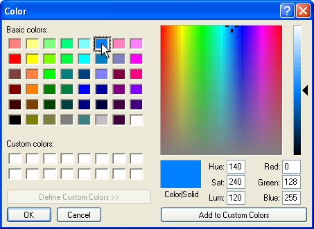
Select a color assignment and click on the OK button.
If the control valve is intended to be a master valve,
click on the Master Valve
checkbox until a checkmark appears in the box.
Click on the OK
button to begin placing the symbol on the drawing screen.
The symbol will appear on the mouse cursor. Drag
the symbol to the desired location on the drawing screen and click
one time with the left mouse button.
Rotate the
symbol to the desired angle and click a second time to complete the
placement process.
Another control valve symbol of the same type will
appear on the mouse cursor. Continue placing additional control
valve symbols as necessary.
Press the Esc
key to end the command and return to the Control
Valves dialog box.
Click on the Close
button to exit the dialog box.
Note:
Set the cost associated with each piece of equipment,
the part number and the tied assembly assignment in the Equipment
Costs command.
Expand or contract
sections as required.
Back to All Topics