Lighting Wire/Cable
Lighting Wire/Cable
Accent Lighting Wire/Cable
Menu: |
Lighting
 Wire/Cable Wire/Cable |
Toolbar Icon: |

|
The Accent Lighting Wire/Cable
command allows you to draw wire or cable from a lighting transformer to
the lighting fixtures. You can change the label indicating the wire
size on the design screen and the color of the wire.
To start adding wire/cable to the drawing
screen:
Click on a wire selection one time with the left mouse
button. You can add, delete or rename
the wire selections.
Under the Wire Settings
header, enter a label to indicate the size of the wire on the design
screen in the Label text box.
Examples of wire size labels are 14, 14 Ga., 14 Gauge.
To assign a to the selected
wire size, click on the Color
button. Click on the color of your choice or enter the Red,
Green, and Blue values in the associated text boxes. Click on
the OK button to accept the
color assignment.
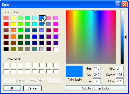
Select a color assignment and click on the OK button.
Enter the resistance in Ohms
per 1,000 feet in the Resistance
text box. Even if you are designing using Metric units of measurement,
enter the Ohms per 1,000 feet.
Enable the Show
Wire Label check box by clicking on the selection with the
left mouse button until a checkmark appears in the box to show the
wire label on the drawing screen. If this feature is disabled, the
wire label will not appear on the screen. If the Show
Wire Label check box is disabled in the Layer
Manager, the labels will not appear on the design screen.
To begin drawing wire on the design, click on the
Draw Wire button.
Set two or more points to draw a piece of wire. You
may press the Esc key to "backup"
and remove points set while drawing wire. Press the Enter
key to end a piece of wire. Continue placing additional wire
as necessary.
If wire from one circuit crosses wire from another circuit, you must
insert a wire hop to prevent the software
from combining the two circuits during lighting calculations.
Press the Esc
key to end the command and return to the Wire/Cable
Placement dialog box.
Click on the Close
button to exit the dialog box.
Note:
You can drag the mouse cursor close to a lighting
symbol and press the right mouse
button to "snap"
onto the symbol. This is the best method to insure the wire
is connected to the lighting symbol.
When drawing wire or cable, the wire must start or
stop within the set Wire Connection
Distance from the insertion point of the lighting symbol. The
Wire Connection Distance is
set in the Lighting
Options command. The default setting is
3 inches (0.25 feet). Depending on the chosen symbol,
the insertion point may be in the middle of the symbol or some other
location. Note the point from which the symbol rotates as you
place it on the drawing screen. The base point of rotation is
the insertion point where the wire must stop or start for voltage
drop calculations to function.
The only exception to this rule is at the transformer location. Wire
from two or more circuits can meet within the connection distance
at the insertion point of the transformer symbol. The software
will ignore the connection distance at the transformer.
You can override the wire size label location on the
design screen using the Properties command.
Select a piece of wire and click on the Override
Label Point checkbox. The wire size label will attach
to the mouse cursor. You can then place the label in a new location
by clicking on the design screen with the left mouse button. To
return the label to its original position, un-check the Override Label
Point checkbox.
Set the cost associated with each piece of equipment,
the part number and the tied assembly assignment in the Equipment
Costs command.
You can change the line type, width and scale of the
Lighting Wire layer in the
Layer Manager.
If the Show Wire
Labels checkbox is disabled in the Layer
Manager, the wire labels will not appear on the drawing screen.
You can use the Select
Layer button in the Layer Manager
in conjunction with the Move to Back
command to move the wire underneath other accent lighting symbols.
Back to All Topics