Pro Contractor Studio Knowledge Base
Import
Menu: |
File
|
The Import command will allow you to import a file from a different format such as an AutoCAD� DWG file. The command displays the AutoCAD� DWG file in a viewer for manipulation prior to importing into a Pro Contractor Studio� drawing file. The viewer is not as fast or as clear as the actual drawing screen. The Import command provides tools to "cleanup" the DWG file and set the paper size, orientation, scale and position prior to importing the drawing to the screen.
To import a different file format:
Start a new drawing using the New command or by selecting a template from the Startup Screen.
Select the Import command from the File menu.
Change to the folder containing the file to import.
Select the type of file to open from the Files of type drop down list. Pro Contractor Studio� will import files with a .dwg or .dxf extension.
Select a file name from the list of files located in the chosen directory or type the file name in the File name text box.
Click on the Open button to insert an image of the drawing into the Import dialog box.
Unit Settings:
The Wizard provides assistance in determining and setting the units of measurement. Click on the Show Wizard button to turn the wizard on and display the instructions. Click on the Hide Wizard button to turn the wizard off and hide the instructions.
Select the units of measurement used to create the .dwg or .dxf file from the DWG Source Units (Wizard off) or Set DWG Units of Measurement (Wizard on) drop down list. Make use of the Measurement tool if necessary to assist in determining the units of measurement used to create the .dwg or .dxf file.
Pro Contractor Studio� requires the units of measurement to be equivalent to one foot or one meter. Select the desired units of measurement for the Pro Contractor Studio� drawing from the PCS Destination Units (Wizard off) or Set Pro Contractor Studio Units of Measurement (Wizard on) drop down list.
Pro Contractor Studio� will convert the source units to the desired destination units during the import process.
DWG Control:
Many times there will be entities scattered about the design screen. The Entity Locator tab will allow you to find these entities and delete the ones that are not necessary to complete your design.
Click on a group of entities in the list. The software will zoom to the center point location of the group of entities. Depending on the location and size of the entities, you may need to zoom in further on an area.
If the selected group of entities are not needed to complete the design, click on the Delete Selected Group icon. Click on the Yes
button to delete all of the entities within the selected group. You
cannot Undo this action. Click on the
No or Cancel
buttons to exit the command without deleting the entities.
icon. Click on the Yes
button to delete all of the entities within the selected group. You
cannot Undo this action. Click on the
No or Cancel
buttons to exit the command without deleting the entities.AutoCAD� drawing files can include hundreds of layers. The Layers tab will allow you to turn off the layers that are not necessary to complete your design, and prevent them from being imported into your drawing.
Click on an entity one time with the left mouse button. The entity will become bold and its layer assignment will be highlighted in the list.
Click on the light bulb icon to the left of the layer name. If the bulb is illuminated , the layer will import into the
drawing. If the bulb is darkened
, the layer will import into the
drawing. If the bulb is darkened
 , the layer will be invisible in
the viewer and will not import into the drawing.
, the layer will be invisible in
the viewer and will not import into the drawing.
Sheet Settings:
An imaginary sheet of paper on which to design is displayed based on the current sheet settings. You may need to adjust the settings to make the drawing to import fit the paper.
Under the Sheet Settings title bar, enter the paper size in the Width and Height boxes and select the units of measurement from the Units drop down menu. You should always enter the width and height measurements as if you were looking at the sheet of paper in the portrait orientation.
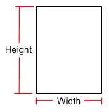
Paper in a Portrait Orientation
You can select a paper size from an existing printer driver by clicking on the Get Paper Size From Printer button. Click on the drop down arrow to
the right of the Select Printer label to view a list of
the installed printer drivers. Select a driver from the list
by clicking on the selection one time with the left mouse button.
Select a paper size from the resulting list and click on the
OK button.
button. Click on the drop down arrow to
the right of the Select Printer label to view a list of
the installed printer drivers. Select a driver from the list
by clicking on the selection one time with the left mouse button.
Select a paper size from the resulting list and click on the
OK button.
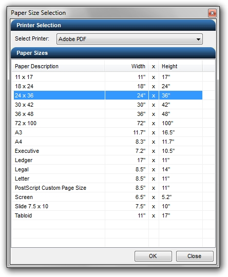
Select paper size from an existing Adobe PDF printer driver.Click on either the Portrait
 or Landscape
 orientation
button to select the paper direction. The orientation of the
paper along with the dimensions are displayed on the right side of
the dialog box under the Sheet Working
Area title bar.
orientation
button to select the paper direction. The orientation of the
paper along with the dimensions are displayed on the right side of
the dialog box under the Sheet Working
Area title bar.Most printers cannot print all the way to the edge of a sheet of paper. A margin is usually set bordering the paper. Enter the margin for the paper in the Border Margin text box. The maximum border size is 1 inch.
The scale is a setting that represents one unit on the paper in relationship to x number of drawing units. For example, suppose the output sheet of paper is 8.5 inches by 11 inches. The drawing is created with the drawing units set to feet. If the selected drawing output scale is 1:10, this means every 1 inch on the sheet of paper is equivalent to 10 feet on the drawing. If the selected output scale is 1:20, every 1 inch on the paper will be equivalent to 20 feet on the drawing.
When entering the output scale for metric units of measurement, the paper is measured in millimeters while the drawing is created with the drawing units set to meters. To print to a scale of 1 meter of paper is equivalent to 100 meters of drawing units (1:100), the Scale in the Drawing Page Setup command would be entered as 1000 mm = 100 units or select 10:1 from the drop down menu. A scale of 1:250 would be entered as 1000 mm = 250 units or select 4:1 from the drop down menu.
Click on the Scale drop down arrow and select the desired output scale, or enter a value for the paper and drawing units for a custom scale setting.
Sheet Offset:
You may need to reposition the imaginary sheet of paper behind the drawing entities. Enter an X and Y value in the Sheet Offset boxes or click on the Move Sheet
 button
to reposition the piece of paper behind the drawing as required.
button
to reposition the piece of paper behind the drawing as required.
Import:
Click on the Import DWG button to begin importing the contents of the file to the design screen, or click on the Close button to exit the command.
Note:
All imported files must have units equivalent to feet or meters to create designs. Make use of the Scale command to resize the drawing if necessary.
The maximum margin size is 1 inch.
You cannot import an Adobe PDF file. A PDF file must be converted to a raster image format and the raster image can then be inserted into a drawing using the Insert Image command.